6 minutes
VXLAN Deployment : Huawei environment
Introduction
In this post, we will discuss VXLAN implementation in a Huawei environment.
I will cover all step of the deployment, from architecture design to implementation. But first, a quick theorical reminder.
VXLAN
Many people know VLAN technology.
VLAN technology, is a layer 2 technology, which allow to logically isolate multiple sub network using the same physical infrastructure. It permit many things, as isolation, QoS, filtering… and a simpliest management of the network.
As said, VLAN is working on layer 2. And it is know that VXLAN operates.
VXLAN is a layer 3 technology. That means, that we will be able to easily transport data from, for example, remote physical sites, with abstraction of layer 2. It also means that we need a working routing.
With Cloud development, and all problematics that comes with it as scalability, availability… VXLAN is a perfect way to solve that. For example, VXLAN is often presented for VM migration between remote site hypervisor.
Why this post?
A few months ago, I started working for a client which need VXLAN implementation. I was not experienced with VXLAN before and everything was new to me.
VXLAN is not a really complex technology to implement, but I have not found many post about implementation.
For my client privacy, I will present a pre production model, that is a representation of the real project (some informations may be hidden). The production infrastructure is about 44 switches and 48 VLANs in total on sites. The aim of the project, was to unify the client physical sites and create a MAN. Each remote site will be connected to a central site which provide L3 routing and Internet access.
All the infrastructure is optical fiber.
Infrastructure environment
Ok, so let’s start.
This schema is our pre production environment, on layer 2 level :
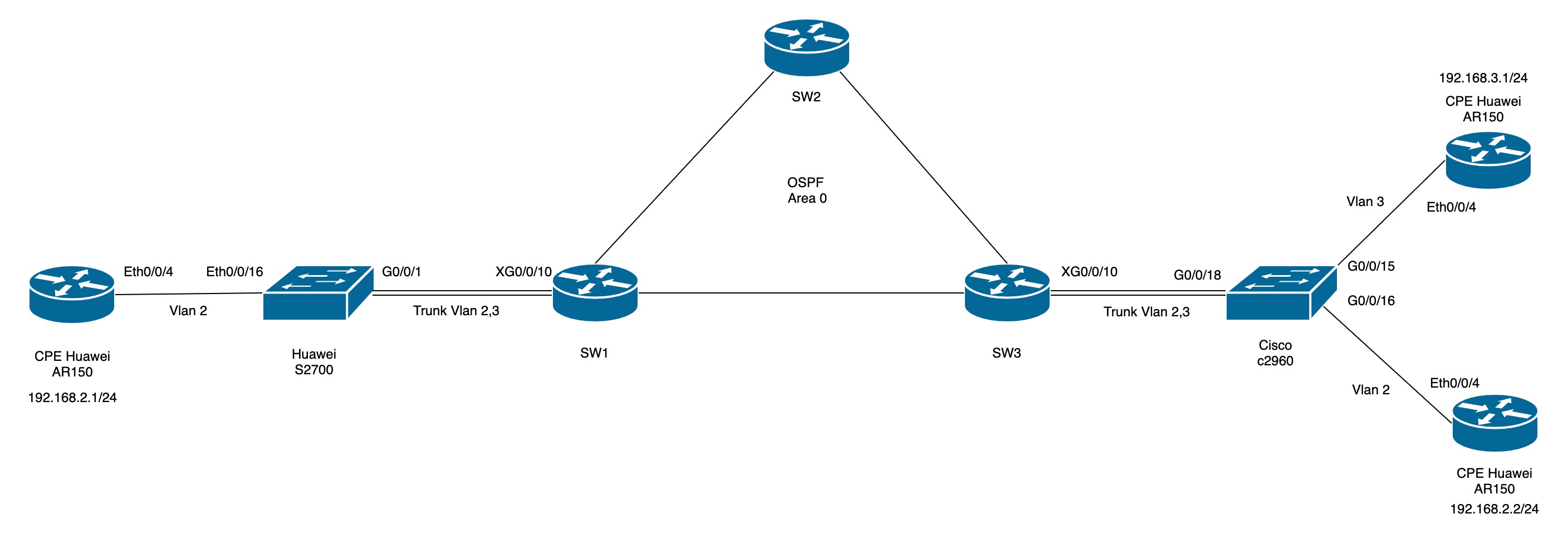
As you can see, we have endoints one each extremity with VLANs 2 and 3. I will come to VLANs configuration after.
And, the layer 3 level :
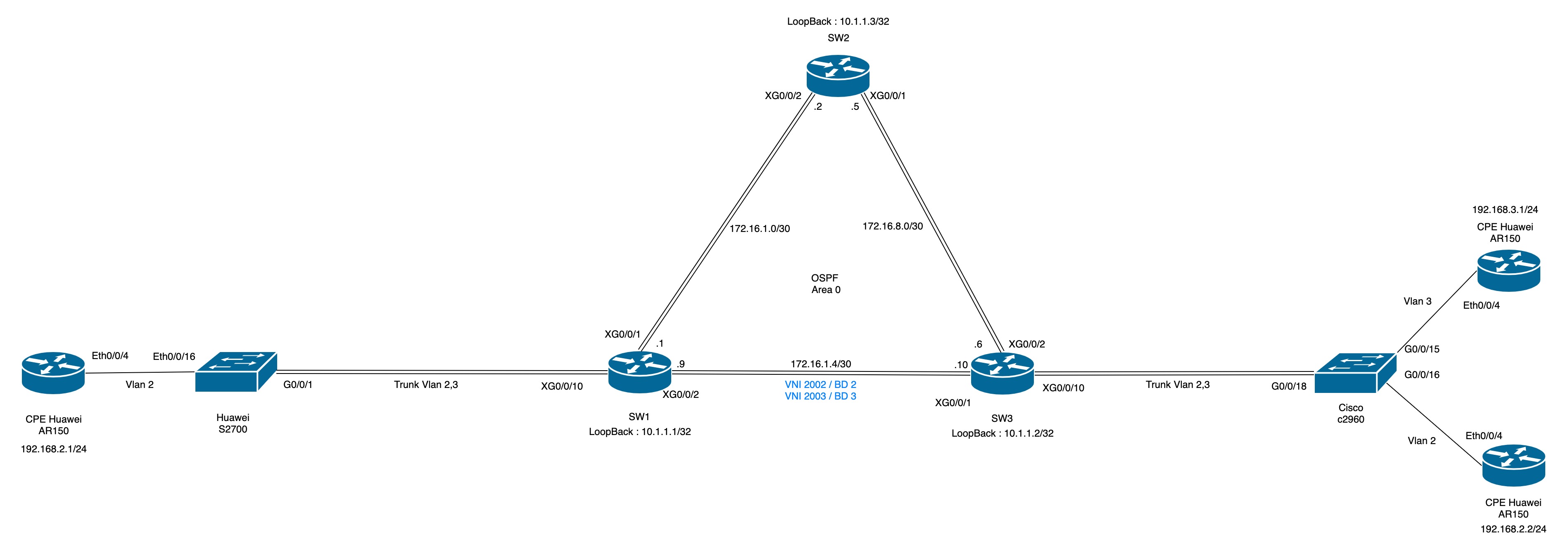
And there are the VXLAN. As you can see, the VXLAN only are on the L3 layer. We will come to the configuration later. The VLANs are encapsulated in the VXLANs tunnels.
Another thing that is not mentionned on the schemas is that the link between SW3 and the Cisco is in LACP mode. So it add some more complexity.
Hardware
Every switches or routers are Huawei, except one, which is a Cisco. This is voluntary, because we will have an LACP trunk in the production envrionment, between the Huawei switch and an another manufacturer switch.
We have : - SW1, SW2, and SW3 : S6730EI switches - CPE : AR150 - Cisco C2960 - Huawei Quidway S2700
VLAN Endpoint
As you seen, we have CPE as endpoints, and two VLANs for this workaround : vlan 2 and vlan 3.
They respectively have 192.168.2.0/24 and 192.168.3.0/24 sub networks.
On the Huawei S2700, the port Eth0/0/16 is in access mode (untag), and G0/0/1 in trunk mode (tag). On the Cisco, G0/0/15-16 are in access mode (untag) and G0/0/18 in trunk mode.
LACP
We set a LACP on SW3, with port XG0/0/9-10.
First, we create the eth-trunk interface :
interface Eth-Trunk1
 port link-type trunk
 undo port trunk allow-pass vlan 1
 mode lacp
And then, we bind our physical interfaces :
#
interface XGigabitEthernet0/0/9
 undo negotiation auto
 eth-trunk 1
#
interface XGigabitEthernet0/0/10
 undo negotiation auto
 eth-trunk 1
#
VXLAN Deployment
So, the first step is to configure our OSPF backbone.
I have chose to set : - a loopback, which will be the router-id - a /30 between SW1, SW2, and SW3
So, once the OSPF area is set, we can create our bridge-domain (BD). On SW1 and SW3 :
bridge-domain 2
 vxlan vni 2002
bridge-domain 3
 vxlan vni 2003
The vni is the VXLAN identifier. We will use is it to set our tunnel endpoints.
Then, I create on SW1 an NVE interface, with loopback IP as source :
interface Nve1
 source 10.1.1.1
 vni 2002 head-end peer-list 10.1.1.3
 vni 2003 head-end peer-list 10.1.1.3
And on SW3 :
interface Nve1
 source 10.1.1.3
 vni 2002 head-end peer-list 10.1.1.1
 vni 2003 head-end peer-list 10.1.1.1
On access network behind SW1, I have nothing on VLAN 3, but it is an example on how to map multiple tunnels.
And the last step, is to bind to our eth-trunk on SW3 :
#
interface Eth-Trunk1.2 mode l2
 encapsulation dot1q vid 2
 bridge-domain 2
#
interface Eth-Trunk1.3 mode l2
 encapsulation dot1q vid 3
 bridge-domain 3
#
On SW1 :
#
interface XGigabitEthernet0/0/10
 port link-type trunk
#
interface XGigabitEthernet0/0/10.2 mode l2
 encapsulation dot1q vid 2
 bridge-domain 2
#
interface XGigabitEthernet0/0/10.3 mode l2
 encapsulation dot1q vid 3
 bridge-domain 3
#
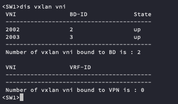
And know, we can check that the VXLAN tunnels are up :
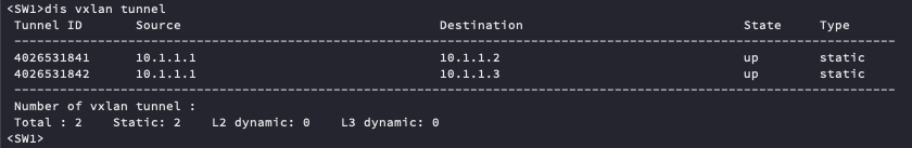
The peers :
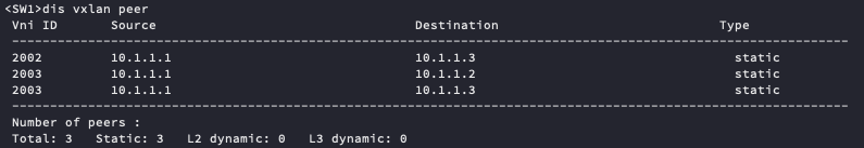
And the
MTU
For some frame size consideration, and because the VXLAN header is bigger than the VLAN header, we change the MTU size and we enable JumboFrames :
interface XGigabitEthernet0/0/1
 undo portswitch
 mtu 9216
 ip address 172.16.1.1 255.255.255.252
Config file generation : python scripting
As said in the begining of this post, I have a lot of switches to configure. So, I have create a simple python script to generate my config files for each sites. I import the informations from a CSV file.
A part of my csv content :
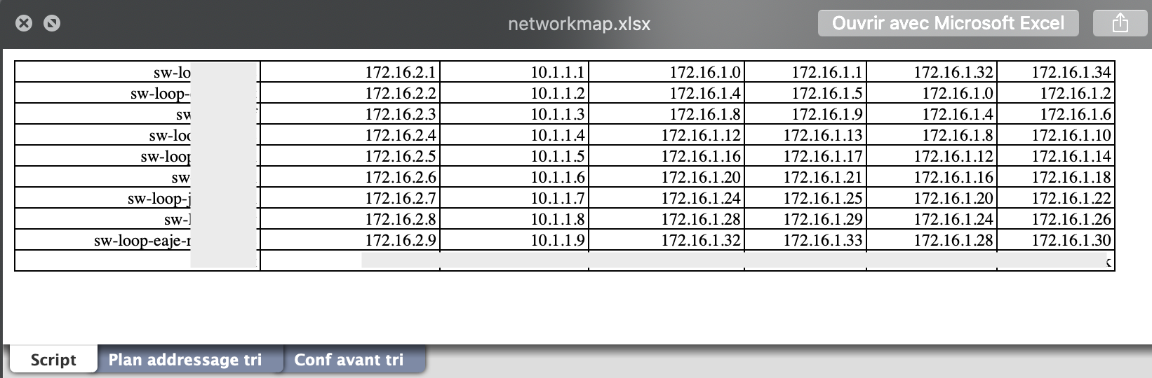
I have the sysname, management IP, Loopback IP, and networks for OSPF area and respective IP interfaces.
I know that it is note perfect, but it do the job :
#!/usr/bin/env python3

import shutil
import xlrd
from shutil import copyfile


sysname_list = []
managementip_list = []
xg1ip_list = []
xg2ip_list = []
loopback_list = []
network1_list = []
network2_list = []


loc = ('networkmap.xlsx')
wb = xlrd.open_workbook(loc)
sheet = wb.sheet_by_index(0)
sheet.cell_value(0, 0)

def populating_list():
    for i in range(9):
        j = 0
        temp = sheet.cell_value(i,j)
        sysname_list.append(temp)
    for i in range(9):
        j = 1
        temp = sheet.cell_value(i,j)
        managementip_list.append(temp)
    for i in range(9):
        j = 2
        temp = sheet.cell_value(i,j)
        loopback_list.append(temp)
    for i in range(9):
        j = 3
        temp = sheet.cell_value(i,j)
        network1_list.append(temp)
    for i in range(9):
        j = 4
        temp = sheet.cell_value(i,j)
        xg1ip_list.append(temp)
    for i in range(9):
        j = 5
        temp = sheet.cell_value(i,j)
        network2_list.append(temp)
    for i in range(9):
        j = 6
        temp = sheet.cell_value(i,j)
        xg2ip_list.append(temp)

def generate_config():
    shutil.copyfile('originalconf.txt', 'config.txt')

    for i in range(9):
        original = open('originalconf.txt', 'r')
        config = open('config.txt', 'w')
        checkWords = ('sysname original', 'ip address 192.168.10.190', 'ip address 172.16.1.1', 'ip address 172.16.1.2', 'ip address 10.1.1.1', 'source 10.1.1.1', 'ospf 1 router-id 10.1.1.1', 'network 10.1.1.1 0.0.0.0', 'network 172.16.1.0 0.0.0.3', 'network 172.16.1.8 0.0.0.3' )
        repWords = ('sysname ' + sysname_list[i], 'ip address ' + managementip_list[i], 'ip address ' + xg1ip_list[i], 'ip address ' + xg2ip_list[i], 'ip address ' + loopback_list[i], 'source ' + loopback_list[i], 'ospf 1 router-id ' + loopback_list[i], 'network ' + loopback_list[i] + ' 0.0.0.0', 'network ' + network1_list[i] + ' 0.0.0.3', 'network ' + network2_list[i] + ' 0.0.0.3' )

        for line in original:
            for check, rep in zip(checkWords, repWords):
                line = line.replace(check, rep)
            config.write(line)
        config.close()
        original.close()
        copyfile('config.txt', sysname_list[i] + '.txt')


populating_list()
generate_config()
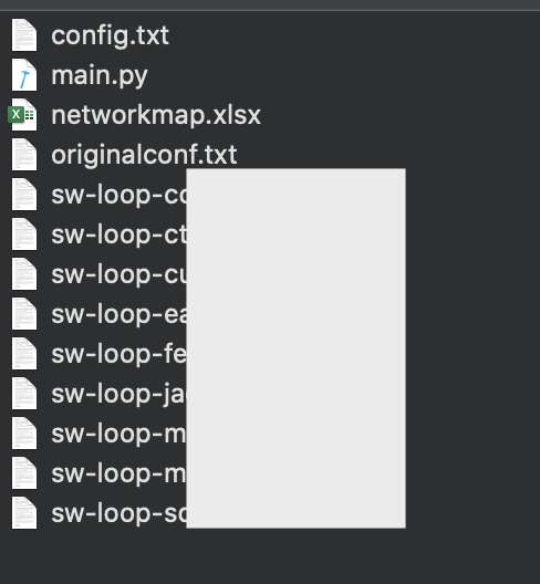
The infrastructure of my folder after launching main.py :
Conclusion
In this workaround, we have set up a simple VXLAN infrastructure, with LACP trunk on one switch in Huawei environment.
Hope it helps!
Sources
https://support.huawei.com/enterprise/en/doc/EDOC1000178188/5f42f6b3/vxlan-network-architecture
VXLAN + LACP :
https://support.huawei.com/enterprise/fr/doc/EDOC1100092871/1cfcb3b7